Plasma ray devices
This page presents images of the plasma ray devices and associated equipment used by Rife in his efforts to affect microorganisms. Since the devices sometimes called “#1” and “#2” are not known or well documented, the images below begin with what is currently known as the “#3” ray device. The devices are shown in approximate date order.
Click on any image for larger version, which will open in a new page.
Ray device “#3”, circa late 1920s - early 1930s

#3 ray device, showing Kennedy radio equipment & additional components. Some individual radio components are owned by specialty collectors, but the full setups in these photographs are lost.

#3 ray device, showing Kennedy radio equipment & additional components, details enhanced.

This image is a closeup of the ray tube from the preceding pictures showing the Kennedy radio equipment.

#3 ray device on workbench, with #2 microscope and Piffard tube. Dated 1932 or later. Kennedy radio at left, on back corner of bench.

#3 ray device on workbench, wide view. Shows edge of #3 microscope and Piffard tube at far left. Kennedy radio is at left back corner of bench. Dated 1933 or later.

#3 ray device with Piffard tube, near end of bed.

Piffard tube hanging over head of bed. The #2 and #3 Rife microscopes are in the background. Dated 1933 or later.

Piffard xray tube, light anode version. This was the model likely used by Rife. It was regassed with helium, and therefore did not emit xray.

Piffard tube, old catalog ad. The tube is made of leaded glass.

Rife with #2 microscope and Piffard tube (see previous 2 pictures). From Popular Science February 1932.
Ray device “#4”, circa early-mid 1930s & onward

#4 ray device. This is possibly an earlier model with fewer adjustment knobs, as compared to the model shown in Rife portion of original 1939 lab film. This device is currently thought to be lost.

#4 ray device used in original portion of 1939 Rife laboratory film. Possible later model with more adjustments on the right side of console. There are two large National type NW oscillator dials on the left side of the console. Kennedy radio equipment in background.

#4 ray device used in original portion of 1939 Rife laboratory film, without Rife in the picture. Possible later model with more adjustments on the right side of console. #3 microscope and ray tube on the right.

Closeup of #4 ray device, from 2nd Crane section added to original Rife 1939 lab film. Possible later device model.
Ray device #5, May 1938 - January 1939

Photograph of Royal Rife and Philip Hoyland with the #5 ray device designed by Hoyland. Dated May 1938. There is no known extant example in existence of this exact model.

Closeup view of #5 instrument in previous photograph. Wires from the ray tube plugged into front of cabinet, top right corner.

Closeup view of flask-type plasma ray tube from #5 instrument in first photograph. Dated May 1938.
“Couche” ray device: possibly late 1930s-1950, exact date unknown

Photo of a ray device. Ownership has been attributed to Dr. James Couche, but without evidence. Wires from the ray tube plug into the top of the cabinet. This device is currently thought to be lost.

Closeup of console of "Couche" ray device. Faintly shows evidence of older prior dial mounting, below & left of center black dial.

Closeup of front end of Piffard ray tube (darkened from heavy use), used with the "Couche" device. The tube gives possible indication of original 1930s-era dating.
“Low” device: possibly late 1930s-1950, exact date unknown

Old ray device as originally found in attic of Mr. Larry Low in 2008. Previously owned by one or more doctors, and stored by Mr. Low for many years. All photos by Alan Luft, and kindly provided by Eric Rowley & Dr. James Bare.

Closeup of front panel of "Low" device. Shows evidence of previous alterations. Wires to the ray tube would have plugged into the top right front corner of the cabinet, just to the right of the milliampmeter. The device operated with a fixed 3.8 MHz carrier wave generated by a Hartley-style oscillator.

"Low" device closeup showing National type N audio oscillator dial (above), and 2-position bandswitch dial (below). Old tuning adjustment dial in the center previously removed.

"Low" device closeup of amplitude dial for adjustment of modulation depth (strength). Above it, the empty round circular location likely held an old "magic eye" for visual confirmation of the correct radio carrier frequency. The RCA magic eye was only manufactured from 1937 through about 1941, and by 1942 had fallen out of favor.

"Low" device closeup of Triplett milliampmeter, 0-300 volts D.C.

"Low" device closeup of timer dial and power output switch.

"Low" device closeup of filament switch, near lower left corner of cabinet front.

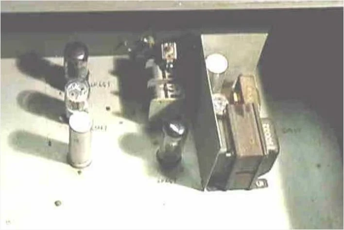
Inside view of "Low" device's circuitry, as originally found in Mr. Low's attic. Prior-drilled empty holes in the chassis indicate the cabinet housed an earlier design.

"Low" device circuitry closeup, upper level left. Easily visible is RCA Radiotron 809 tube.

"Low" device circuitry closeup, upper level right. Light grey condenser (capacitor) on far right connects to audio oscillator dial at front of device.

"Low" device circuitry closeup, lower level.
Device photograph found in “Low” device: possibly late 1930s-1950, exact date unknown

This is an image of an original photograph found inside of the "Low" device, of a different ray machine. Wires from the ray tube plug into the top of the cabinet. Photos by Alan Luft, and kindly provided by Eric Rowley & Dr. James Bare. This device is currently thought to be lost.

Closeup of the console. Top row, from left to right: likely a milliampmeter; National Co. audio frequency adjustment dial (actual frequencies not indicated); and a modulation depth (strength) meter. Bottom row from left: two apparent 4-position range switching dials; and three switches. Carrier wave frequency for this device is unknown.

Closeup #1 of the ray tube shown in previous photograph.

Closeup #2 of the ray tube shown in previous photograph.
Gruner device (schematic), as assembled in 1942

Schematic drawn by Dr. Oskar Gruner (Montreal, Canada) of a plasma ray device, parts of which were sent to him in 1942 by Dr. Milbank Johnson from San Diego. The device had parts added and was reassembled in Canada; it emitted only one audio frequency on a fixed carrier wave. This schematic was sent to John Crane in 1953; some notes added by Crane. Actual device was destroyed, no photos available.

A modern copy of the original Gruner schematic as redrawn by Scoon & Harrison in 2002. Notes added by Crane not included. Easier to read due to poor resolution of the original schematic.
British Rife Group “Scoon” ray device, built by Verne Thompson c. 1954

Original photo of plasma ray device as advertised at the old rife.org website. Acquired by the U.K. Rife Research Group in early 2000s, and subsequently analyzed by Aubrey Scoon, after whom the device is named. New dating of its Eico audio frequency generator places it at 1954 or later, and almost certainly built by Verne Thompson. Thompson was a radio engineer that worked with Rife for many years.

"Scoon" device after purchase, set up with a non-original, modern Russian-made Nazarov plasma tube.

Closeup of "Scoon" device, front of cabinet. The device operated with a fixed 3.3 MHz carrier wave.

Closeup of original plasma tube that came with the "Scoon" device. Pyrex white oval is faintly visible at bottom of picture, indicating manufacture from laboratory glassware.

Modern Russian-made Nazarov plasma tube used by Scoon to test and analyze the device.

Closeup of Nazarov plasma tube used by Scoon.

Closeup of the three dials on the front panel of the "Scoon" device. From left to right: bandswitch, audio frequency selection, and modulation strength.

This dial has four positions for selecting an audio frequency band (commonly called a "bandswitch").

This dial adjusted the audio frequency used to modulate a radio carrier frequency. The dial shows setting positions, not the actual frequencies. The user would have needed to know which settings to use for the various disease conditions.

This dial adjusted the strength (sometimes called "depth") of the modulation of the audio frequency upon the carrier wave.

The back side of the "Scoon" device, showing two levels of electronics. The top level is unfortunately in the shadow of the top of the case.

The radio frequency output portion of the electronics from the "Scoon" device, from the lower level of the case; it used a fixed Hartley oscillator design.
This is the audio output section from the top level of the "Scoon" device. It consists of electronics from an Eico 377 audio frequency generator, which were available in kit form beginning in the very early 1950s. This unit contains Eico's later "2-gang" capacitor model, which dates from at least 1954 onward.

For comparison to previous photo from the "Scoon" device (turned 180 degrees side-to-side), this is an Eico 377 silver-faced "2-gang" audio frequency generator. This 2nd model dates from at least 1954 onward.

This is the earliest model of the Eico 377 audio frequency generator, dating prior to at least 1954. It contains a "4-gang" capacitor, which does not match the "Scoon" unit.
Thompson ray device, 1954-56

Device built by Verne Thompson about 1954 or shortly thereafter, and likely after the "Scoon" device above. The plasma tube shown in this photo may not be original. Like the "Scoon" device, this design used a Hartley oscillator for a fixed radio carrier frequency (currently unknown), and an Eico model 377 generator for audio sine wave frequencies. All photographs kindly provided by Dr. James Bare.

Closeup of front of Thompson device cabinet.

Closeup of the three dials used for tuning and modulation. The left bandswitch dial positions for audio frequency range are labeled A-D, different than the 1-4 markings on the corresponding "Scoon" device dial. The middle dial adjusts the audio frequency, and the right dial the modulation level.

This chart lists a number of disease and pathogen names, with the corresponding bandswitch and audio dial settings to be used for each one.

Closeup #1 of the large plasma tube pictured with the Thompson device, possibly not original for the 1950s dating of this device.

Closeup #2 of the plasma tube, showing a better view of the electrodes.

This image shows the entire circuitry for the Thompson device, most of which is on one board.

A closeup of the Thompson device circuit board showing the Eico 377 audio oscillator portion. Thompson rearranged the components of the kit, as compared to the standard Eico layout (seen "Scoon" device section above). Roger Blain explains that in this particular circuit, Thompson appears to have eliminated a tube associated with square wave production, thus allowing only audio sine waves to be generated.

A further closeup of the Eico audio oscillator portion of the Thompson device. It shows the 2-gang capacitor, which dates this device 1954 or later (see "Scoon" section above).
AZ-58 ray devices (6 models), late 1953 - 1957

AZ-58 model 1, September 1953. Dating of these devices follows the analysis given in Roger Blain's paper "AZ-58 Revisited" (see the Technical & Patents section of the website for a copy and more details). The image of this model's interior is the only photo currently available. Most of the AZ-58s were designed by Verne Thompson for John Crane's company Allied Industries. This model used a fixed carrier frequency of 4.15 MHz produced by a Hartley oscillator. The square wave audio frequency range 50 Hz - 6 kHz was produced with use of a 3-position bandswitch, and the modulation amplitude was not adjustable. This model's components were fitted onto a relatively narrow one-level 19" chassis (case).

AZ-58 model 2, 1953. This model used a fixed carrier frequency of 4.15 MHz produced by a Hartley oscillator. The square wave audio frequency range 50 Hz - 6 kHz was produced with use of a 3-position bandswitch, and the modulation amplitude was not adjustable. This and subsequent models used a wider chassis (case) than the model 1.

Another view of the AZ-58 model 2, with plasma tube. The tube may not be original for this device.

AZ-58 model 3, 1953. This image of the interior is the only photo currently available of this model. This model used a fixed carrier frequency of 4.15 MHz produced by a Hartley oscillator. The square wave audio frequency range 50 Hz - 6 kHz was produced with use of a 3-position bandswitch, and the modulation amplitude was not adjustable.

AZ-58 model 4, dated 1957. This device was the model used by Dr. Robert Stafford in Dayton, Ohio. It used a variable carrier frequency of 3.1-3.3 MHz produced by a Hartley oscillator. The square wave audio frequency range 50 Hz - 6 kHz was produced with use of a 3-position bandswitch, and the modulation amplitude was not adjustable.

Inside view of AZ-58 model 4.

AZ-58 model 5, 1957. It had variable carrier frequency capability, and was used at 4.68 MHz produced by a Hartley oscillator. The square wave audio frequency range 50 Hz - 6 kHz was produced with use of a 3-position bandswitch, and the modulation amplitude was not adjustable.

An older photo of the AZ-58 model 5, with probable original plasma tube.

AZ-58 model 6, 1957. Photo reproduction is poor, but included here as a record. This model had variable carrier frequency capability, and was used at 4.68 MHz produced by a Hartley oscillator. The square wave audio frequency range 16 Hz - 6 kHz was produced with use of a 5-position bandswitch, and the modulation amplitude was not adjustable.